I’ve bought a dual usb car charger recently with the intention of modifying it. My intent is to use this charger to charge two Android phones at the same time with the maximum allowable current.
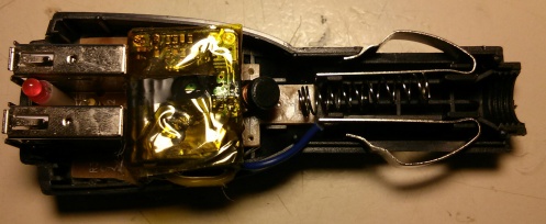
Here you can see the charger. The connector to the left included a fuse. The eight-legged IC in the middle is a MC34063. You can see the inductor at the top. I don’t think this circuit comes anywhere near the advertised 1000mA.
I’ve bought a bunch of integrated switching mode DC/DC-converters. They are named KIM-3R35 and are quite cheap with the following specs:
- Vin = 9V – 40V
- Vout = 3.3V
- Iout = 5A
There is a Russian page with handy formula to calculate the output voltage etc. Google it!
I removed the heatsink and a lot of potting compound. The voltage divider for the voltage feedback is at the top right. You can see the “103” meaning 10kΩ resistor at the top right. There was a 18kΩ resistor previously. The 10kΩ resistor gives me 5.38V which is quite near to the absolute maximum voltage of 5.5V which some usb-connected ICs can handle.
Unfortunately, it didn’t work. The converter wouldn’t start up. I tried with 24V and i got a whining noise out of it. The output voltage was fluctuating wildly from 0V to 5V and the converter heated up. After reading the datasheet i decided to add an additional output capacitor which did the trick. Apparently the builtin ceramic output capacitors lose so much capacity when going from 3.3V to 5V that the converter is not stable anymore.
But it still wouldn’t start with 12V. After reading some more i decided to change the undervoltage lockout level. You can see the responsible resistor Rkff at the bottom. Originally it was a 300kΩ resistor. I tried out an 160kΩ resistor and left it in as it was working perfectly with 12V.
The usb connector had to be modified to make the phone pull more input current. Android phones want D+ and D- connected to each other with a < 200Ω resistor. There was already a blob of solder over D+ and D-, so i had nothing to do here.
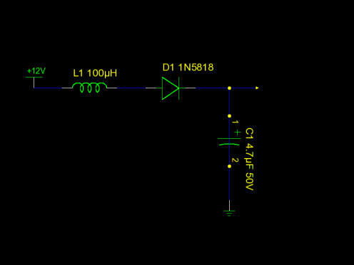
I salvaged parts from the old converter to build an input filter. The value of the inductor is just a guess.
After some testing i finally assembled everything. I secured the opened connections with kapton tape. The connections from the converter to the pcb were made with common Litz wire. I protected the solder joints with Plaast which is similar to glue. And that’s it! A dual usb car charger with 5A output combined.


